Contents
Index
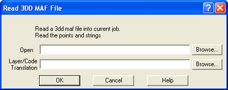
Read 3DD MAF File
This option will read a 3DD data file into the job.
Open
Enter the name of the Input 3dd file. These files generally have a .MAF extension.
The program will read all the points and strings from the file into the current job.
Layer Code Translation
Enter the name of the Layer/Code Translation file to be used. This file can specify
the layers and codes to be used for the input points and strings.

The MAF file format takes the form:
- HM - feature definition file (where H indicates header information)
- HF - false origin, <Easting offset> <Northing offset> <Height Offset>
- HS - default plot scale
- HA - accuracieshorizontal & vertical in metres
- HR - resolution
- HQ - combination of source, accuracies, date, job descriptive
- HW - blank and not known, command to write map header
- F - Line feature
- FP - Spot Heights (Points, P records to follow)
- P - Point record
And then into the feature header followed by points:
F - String feature
F <dim> [height] <code> <src>
<dim>
= 3 for 3 dimensional point values
= C3 for closed feature, 3 dimensional point values
= F2 for 2 dimensional values (Z value to follow)
= CF2 for closed feature 2 dimensional values (Z to follow)
[height] = Z value of points, only present when dim=F2, CF2
<code> Feature Definition Code is something like ‘2 2 2 0’,
four numbers separated by one space.
<src> = source of capture (A= automatically generated, digit=nth data source)
e.g. F 3 2 4 2 0 1
F = line feature and 3D, 2 2 4 0 feature code, 1 source (of capture)
FPSpot Heights
FP <dim> <code> <src
<dim> = 3d point values, 2 for 2d values
<code> Feature Definition Code is something like ‘2 2 2 0’,
four numbers separated by one space.
<src> = source of capture (A= automatically generated, digit=nth data source)
e.g.FP 3 2 2 2 0 1
FP = point feature and 3D, 2 2 2 0 feature code, 1 source (of capture)
Feature Definition Code is always four numbers, each ranging from 0 to 15.
One or more spaces separate the groups.
Strings
String/Line features will be inserted into the job as strings of type ‘Traverse’.
The code e.g. ‘3 2 2 2’ will be written to the string name. The other string
attributes will default to ‘ByLayer’.
Points
Points are read into the job, the false origin is added to each point co-ordinate
and it is inserted into the job at the next available point number.
The Point code will be set to the code on the ‘F’ or ‘FP’ line, e.g. ‘3 2 2 2’.
The other point attributes will default to ‘ByLayer’.
Layer/Code Translation
The user can provide a ‘Layer Translation’ file which can convert data being read
from a 3dd file onto certain layers. It can also translate the codes.
e.g. '2 4 2 0 1’ might be translated to TB01.
Points
A point which is on a 3dd feature (CF, FP or F) and has a matching code field will be
translated onto the specified layer with the specified code. Note that point contourability
can be controlled with the Point_contourable=”N” option.
Strings
A string which is on a 3dd feature (CF, FP or F) and has a matching code field will be
translated onto the specified layer with the specified code(written to string name),
the specified string colour and the specified line style.
A sample translation file is shown here.
<?xml version='1.0'?>
<!-- 3dd to acsp translation file -->
<config>

    <3dd_translation>
        <3dd type="FP" code="3 1 1 0" Descr="Ground pt."/>
        <ACSP Layer="Gro" String_Name="Gro" Point_Code="Gro" Colour="#00ff00" String_Type="Traverse" Style="1" Point_contourable=”N”/>
    </3dd_translation>
    <3dd_translation>
        <3dd type="FP" code="3 1 2 0" Descr="A/T pt." />
        <ACSP Layer="ATp" String_Name="ATp" Point_Code="ATp" Colour="#00ff00" String_Type="Traverse"  Style="1" />
    </3dd_translation>

    <3dd_translation>
        <3dd type="F2" code="2 1 2 0" Descr="Contour" />
        <ACSP Layer="Ctr" String_Name="Ctr" Point_Code="Ctr" Colour="#ffff00" String_Type="Traverse"/>
    </3dd_translation>

    <3dd_translation>
        <3dd type="F" code="3 2 3 1" Descr="Embankment - Top" />
        <ACSP Layer="BT" String_Name="Ctr" Point_Code="Ctr" Colour="#ff0000" String_Type="Discon"  Style="2" />
    </3dd_translation>

</config>
